LTE RADIO INTERFACE
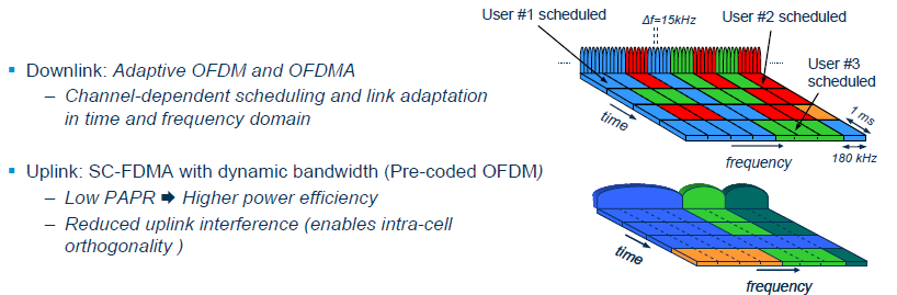
The LTE radio interface is based on OFDM (Orthogonal Frequency Division Multiplex) and OFDMA (Orthogonal Frequency Division Multiple Access) in DL and SC-FDMA (Single Carrier Frequency Division Multiple Access) in UL. These techniques are well suited for flexible bandwidth operation. This enables operators to deploy LTE in different regions with different frequency bands and bandwidths available.OFDM also shows very good performance in highly time disperse radio environments (i.e. many delayed and strong multi path reflections). That is because the data stream is distributed over many sub-carriers. Each sub-carrier will thus have a slow symbol rate and correspondingly, a long symbol time. This means that the Inter Symbol Interference (ISI) is reduced.
The users in DL are separated with OFDMA, which means that each user has its own time- and frequency resources.
The uplink transmission technique, SC-FDMA, is realized in a similar manner as for the downlink (OFDM) and is also called DFTS-OFDM (Discrete Fourier Transform Spread – OFDM). The
time domain structure is also similar in uplink and downlink. SCFDMA has much lower PAPR (Peak to Average Power Ratio) than OFDM. This is one of the reasons for the choice of SC-OFDM for the uplink since the power amplifier in the UE can be made more power efficient and manufactured at a lower cost.
In addition to that, both FDD (Frequency Division Duplex) and TDD (Time Division Duplex) is supported, which opens up for deployment in both paired and unpaired spectrum. In FDD, different frequency bands are used for UL and DL. In TDD the UL and DL transmissions are separated in time. There are pros and cons with both methods. TDD has some more overhead and latency, due to the frequent switching in time. On the other hand, the TDD mode enables radio channel reciprocity, which means that UL measurements can be used for DL transmissions, and vice versa. The TTD mode is also simpler to deploy in areas with limited available spectrum since it can utilize unpaired frequency bands
A half duplex FDD mode (HD-FDD) is also defined, where the UE does not have to transmit at the same time as it receives. Therefore, more cost effective UEs can be manufactured since a duplex filter
is not needed.
The radio resources are defined in the time- and frequency domain and divided into so called resource blocks. Dynamic channel dependent scheduling allocates a number of these time- and
frequency resources to different users at different times.
Link adaptation adapts the modulation scheme and coding rate to the varying radio channel condition.
HARQ (Hybrid Automatic Repeat and Request) caters for very quick layer 2 re-transmission functionality. In addition, ordinary ARQ is implemented in the RLC layer.
The LTE radio transmissions are based on a very short TTI (Transmission Time Interval) of 1ms, which speeds up the operation of all of the above functions. The short TTI also reduces the radio interface latency, which is one of the main concerns in the LTE development.
facebook page
In order to increase the spectrum efficiency, capacity and overall data rates the use of multiple antennas, MIMO (Multiple Input Multiple Output) is included in the standard. With these multiple
antennas and advanced signal processing such as spatial multiplexing, the radio channel can be separated into several layers, or “data pipes”. Up to four layers can be utilized. This corresponds to up to four times higher data rates for a given bandwidth.
The maximum number of Resource Blocks that can be allocated is 100. The 10 remaining RBs (since 20 MHz corresponds to 110 RBs) are needed as guard bands.
LTE physical-layer specification supports any bandwidth in the range 6 RBs to 110 RBs in steps of one RB

UE states and area concepts
LTE is developed to have a simpler architecture (fewer nodes) and less signaling (fewer messages) than UTRAN. Also, the number of states which the UE can be in (corresponding to RRC states) are
reduced from 5 in UTRAN (DETACHED, IDLE, URA_PCH, CELL_FACH, CELL_DCH) to only 3 in E-UTRAN (DETACHED, IDLE and CONNECTED).
Furthermore, the area concept is somewhat simplified in LTE compared to UTRAN. In LTE only one area for idle mode mobility is defined; the Tracking Area (TA). In UTRAN, Routing Area (RA)
and UTRAN Registration Area (URA) is defined for PS traffic and Location Area (LA) for CS traffic.
When a UE attaches to the network it is assigned an IP address from a P-GW. The IP-address is kept regardless of if the UE enters idle mode or not as long as it is attached to the network, but is
released if the UE detaches from the network.
