Showing posts with label GSM. Show all posts

VAMOS (Voice services over Adaptive Multi-user channels on One Slot, Modulation and Power Control for Vamos) IN GSM part3

BY engineer :abdallah Saleh 

Adaptive QPSK (AQPSK) Modulation

In 1986 P. Laurent showed that Gaussian Minimum Shift Keying (GMSK) phase modulation could be approximated by Binary Phase Shift Keying amplitude modulated pulse.

VAMOS extends Laurent’s approximation method to represent the superposition of two GMSK signals as a single AQPSK modulated signal.

Symbol Rotation:

The modulating symbols are continuously rotated with 𝜑 radians per symbol to avoid transitions through the origin (ensure that the envelope of the signal does not go instantaneously close to zero). This minimizes the variations in the modulating signal which in turn minimizes the linearity requirements of the amplifier.
(i.e. each phase modulated symbol is additionally phase shifted by 𝜑 radians per symbol).

Symbol rotation φ depending on modulation:


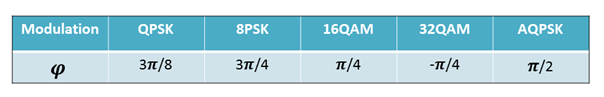
AQPSK use π/2 symbol rotation to imitate GMSK, so legacy GMSK SAIC handsets can receive them separately.

Pulse Shaping:

The process of changing the waveform of transmitted pulses; its purpose is to make the transmitted signal better suited to its purpose or the communication channel, typically by limiting the effective bandwidth of the transmission. 
By filtering the transmitted pulses this way, the inter-symbol interference caused by the channel can be kept in control. In RF communication, pulse shaping is essential for making the signal fit in its frequency band.

facebook page 
                                     Engineering-Academy

 VAMOS DL Power Control

VAMOS Sub-channel Power Control feature adapts the AQPSK modulation constellation to distribute the downlink transmit power between the two sub-channels of the AQPSK modulated carrier. Extra power can be distributed to one of the sub-channels, at the expense of the paired sub-channel. This mechanism is important since it allows legacy mobiles to operate in VAMOS mode. 
The position of the AQPSK symbols, and thus the power distribution between the sub-channels, defined by the Sub-channel Power Imbalance Ratio (SCPIR), are controlled by the VAMOS Sub-channel Power Control.

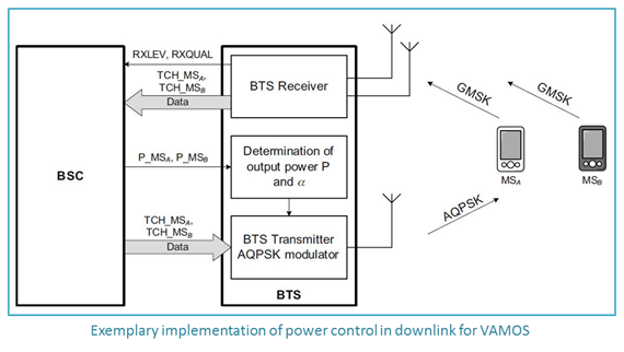
Power Control in downlink for VAMOS is done in two successive stages:

-Determination of the required transmit power levels for both mobile stations MS-A and MS-B according to the radio link measurement reports (RXLEV and RXQUAL) received from these mobiles. The BSS determines the power level P MSA required for MS-A in the first sub-channel and P MSB for MS-B in the second sub-channel.
-Determination of the corresponding AQPSK signal constellation and output power for the AQPSK signal. A control unit in the BTS computes a combination of output power P and α that gives the required combination of P MSA and P MSB in downlink based on the following relationship:   P = P MSA + P MSB = P × cos2 α + P × sin2 α

facebook page 
                                     Engineering-Academy

VAMOS MS Categories:

For several years now, many mobiles have been equipped with SAIC receivers to improve their resistance against inter-cell interference, i.e. not even with VAMOS in mind. 
In other words, when VAMOS gets deployed one does not have to wait for special VAMOS capable devices to reach a critical mass before the benefits can be seen. However terminals that support VAMOS feature increase performance of the BSS VAMOS feature.
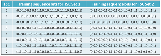
Legacy Non-SAIC:
-Don’t support SAIC algorithm or TSC Set 2
-Can’t be paired with a legacy non-SAIC MS or legacy SAIC MS.
-May be multiplexed on the VAMOS sub-channel in the case of much power offset.
Legacy SAIC:
-Support SAIC algorithm but not support TSC Set 2
-Does not require much power offset.
VAMOS level I:
-Support SAIC algorithm and TSC Set 2
VAMOS level II:
-VAMOS II user devices must cope with strong negative SCIPR values, which will likely require implementation of joint detection techniques in the receiver. Therefore VAMOS I and II requirements will differ by verifying voice performance at different SCPIR proof points. VAMOS I user devices will be tested at SCPIR = -4dB, 0dB and 4dB, whereas VAMOS II user devices will need to fulfill reference performance additionally at SCPIR = -8dB and SCPIR = -10dB.
The VAMOS-aware mobiles are expected to be served on the weaker sub-channels when being multiplexed with legacy mobiles.

Sub-channel Power Imbalance Ratio (SCPIR) is defined by; 
Assuming that MS-B receives the quadrature component and MS-A the in-phase component of the AQPSK signal.

facebook page 
                                     Engineering-Academy

to understand the VAMOS read other parts 

VAMOS (Voice services over Adaptive Multi-user channels on One Slot) IN GSM part2

VAMOS  (Voice services over Adaptive Multi-user channels on One Slot) IN GSM part2

BY engineer Abdullah Saleh
 

Training Sequences :


as mentioned in the part 1  the definition of the Training sequences the below part is explain  the Use of Training sequence in Equalizers:
-As the information will be distorted due to time dispersion problem in air interface, the TSC will be distorted too.
-The channel estimator correlates the stored TSC with the received TSC to estimate the channel impulse response.
-The signal generator generates versions of all possible data sequences that could come from the transmitter.
-The generated signal then pass to a channel model which is a simulation of air interface to calculate the expected received data of the estimated transmitting data.
-The Viterbi algorithm will compare the actually received data with the output of channel model, if the received distorted data has matched the simulated distorted received data, then the locally generated data is the same as the data that was actually transmitted. And if not the process will repeated with different signal generator sequence of data.

Use of Training sequence in VAMOS:

-As cross-correlation properties of the existing (legacy) eight TSCs are not ideal, this leads to additional interference experienced by the MS. The legacy TSC set is referred to as “TSC set 1”.
-In order to improve the correlation properties a new improved set of training sequences “TSC set 2” was specified. The new set of training sequences has been found based on computational simulation work in order to obtain the best possible result with respect to cross correlation properties between existing and new training sequences.
-When using “TSC set 1” the TSC must exhibit low cross-correlation and good auto-correlation in the presence of the other sub channel.
-When using “TSC set 2” the multiplexing is done by taking two TSC with the same index in both sets.


to understand the VAMOS read other parts 

facebook page 
                                     Engineering-Academy


VAMOS (Voice services over Adaptive Multi-user channels on One Slot) IN GSM part1

VAMOS

BY engineer :abdallah Saleh 

VAMOS stands for Voice services over Adaptive Multi-user channels on One Slot. The idea here is to increase the voice calls capacity supported by GSM network. It is possible to use one time slot for four voice calls/services
The feature VAMOS is specified in 3GPP release 9.
VAMOS assign the same GSM physical channel (ARFCN-TDMA frame number-Time Slot) into two users simultaneously.
The GSM channel could be:
-Full Rate Channel
-Two Half Rate Channels
-Two VAMOS Full Rate Channels
-Four VAMOS Half Rate Channels
-One Half Rate Channel and Two VAMOS Half Rate Channels
-One VAMOS Full Rate Channel and Two VAMOS Half Rate Channels

VAMOS Advantages:

1-Doubling of voice calls per transceiver 

Increased call capacity per transceiver gives operators an efficient means to handle voice traffic growth in their networks without adding more TRXs.
Avoiding additional TRX’s results in savings in BTS HW investments, energy consumption and BTS foot print.

2-Free up capacity for EDGE data services

VAMOS reduces the number of time slots needed for voice services. This allows more time slots to be allocated for EDGE services.
Note: EDGE can carry a bandwidth up to 236.8 Kbit/s for 4 timeslots (theoretical maximum is 473.6 Kbit/s for 8 timeslots) in packet mode.

3-Free up spectrum for new technologies

For example UMTS900 (reframing 25 GSM 200 KHz frequency channel into 5 MHz UMTS Carrier) or LTE which allow for flexible operations in different spectrum bands.

VAMOS Disadvantage:

1-The parallel signal transmission of the two multiplexed users causes interference for one another, affecting speech quality if not properly controlled.
2-Call Drop Rate increased due to multiplexing of different MSs types.

facebook page 
                                     Engineering-Academy

How VAMOS can differentiate between two users?

VAMOS transmits the combination of two signals at the same time over the same channel, each with a different orthogonal TSC’s (Training Sequence Code). 
Each of the two MSs that receive the data stream at the same time use their knowledge of their individual TSC to reconstruct their own part of the signal, effectively filtering away the second data stream as noise. 

Up-Link Operation:

Transmitter (MS): use the existing GMSK modulation scheme. In other words, no new transmitter elements are required in mobile devices. 
Receiver (BTS): different receiver algorithms may be used, that is Space Time Interference Rejection Combining (STIRC), Successive Interference Cancellation (SIC) or Joint Detection (JD) to receive both orthogonal sub-channels distinguished by their individual training sequences. Another option is to use two independent GMSK receivers for each sub-channel.

Down-Link Operation:

Transmitter (BTS): use AQPSK modulation technique to be able to transmit two calls at the same time.
Receiver (MS): use 3GPP Downlink Advanced Receiver Performance (DARP) which is also known as Single Antenna Interference Cancellation (SAIC) algorithm to correctly demodulate downlink Signal.

Training Sequences 

The training sequence code (TSC) or Channel Sounding Bits is a known 26-bit pattern placed in the middle of normal burst. TSC has eight fixed formats, which are represented by TSC ranged 0:7 respectively. The eight sequences are stored in all MS receivers to be used for Bit Synchronization and for Channel Estimation.
Because of TSC at the middle of time slot it also called Midamble. By having TSC there, the chances are better that the channel is not too different when it affects the training sequence compared to when the information bits were affected. If TSC was at the start of a burst, the channel might have changed by the end of the burst, and the same thing if it was at the end.
If MS have read SCH, it must get the TSC (Training Sequent Code) to correctly read the information on the downlink common signaling channel. TSC number is linked to the Base Station Color Code (BCC) of the cell. So one of the functions of BSIC is to inform MS of the TSC adopted by the common signaling channel of the cell.

to understand the VAMOS read other parts 

facebook page 
                                     Engineering-Academy

3G Network Planning- Detailed UMTS planning capacity input analysis (Part 6)

Before you read this part in 3G Network  Planning you should read the below Parts in first

capacity input analysis

it is one of the most important step in any dimensioning process is defining the input data and it  is the second step after coverage dimensioning .

1-calculate traffic model 

traffic model is a means of researching the capacity features of each service type and the QOS expected by the users who are using the service from perspective of data transmission.

1.1:Grade of service 

The Grade of Service can be measured using different sections of a network. When a call is routed from one end to another, it will pass through several exchanges. If the Grade of Service is calculated based on the number of calls rejected by the final circuit group, then the Grade of Service is determined by the final circuit group blocking criteria. If the Grade of Service is calculated based on the number of rejected calls between exchanges, then the Grade of Service is determined by the exchange-to-exchange blocking criteria. 
The Grade of Service should be calculated using both the access networks and the core networks as it is these networks that allow a user to complete an end-to-end connection.
 Furthermore, the Grade of Service should be calculated from the average of the busy hour traffic intensities of the 30 busiest traffic days of the year. This will cater for most scenarios as the traffic intensity will seldom exceed the reference level.
The grade of service is a measure of the ability of a user to access a trunk system during the busiest hour. 
The busy is based upon customer demand at the busiest hour during a week month or year.
Grade of service=(number of lost calls)/(number of requsted calls)

1.2 user profile

It is about avg call duration and number of requsted calls per day and srvice rate which will use.
It is different according to economical distribution for this city.

1.2.1 services rates 

Service rate Kbps
12.2
64
128
384
Circuit switching
No
no
Packet switching
No
For  each service rate must identify number of users and user profile as traffic
 Per user in Kb per hour or average  number of calls and average call duration in minute.
Note : 12.2 Kbps circuit switching is voice calls so it have the most number of users .
Erlang=(bit transmitted)/(total capacity)
example: if we have 80 Kb per hour so 
erlang = 80*1000*8/64000*60*60.

1.3 Speed of the user

Speed of the user is very important parameter which affect the signal to noise ratio for each service (Eb/N0)
Speed
Eb\No (circuit switching 12.2kbps)
Eb\No(circuit switching 64kbps)

Eb\No(packet switching 64kbps)
0
5.1
1.7
1.5
3
11.9
9.2
6.2
50
9.4
6.4
6.3
120
7.2
3.8
3.4


Speed
Eb\N0
(circuit switching 12.2kbps)
Eb\N0
(circuit switching 64kbps)
Eb\N0
(packet switching 64kbps)
Eb\N0
(packet switching 128kbps)
Eb\N0
(packet switching 384kbps)
0
5.1
5
4.7
7.9
11.4
3
13.4
7.78
3.9
7.2
10.8
50
10.8
15
11.4
9.7
11.3
120
7.8
10.4
9.7
8.8
12


1.4 area type

It is a parameter which effect on  gama  and ioc_ior values 
Area type
Gama
Ioc_Ior

Dense urban
0.7
2.9
Sub urban
0.5
2.9
Urban
0.6
2.9
Rular
0.4
1.99
Dopen
0.3
1.9


1.5. Loading Factor (ETA)

The loading factor ETA  take values between 0% to 100% .
for example if ETA = 50 % it mean  that there are 150 % increase  of interference  above  the introduced one by home user alone.
The inverse of  the factor (1 +ETA) is sometimes known as the frequency reuse factor .
the frequency reuse factor  is ideally equal to one in the single  in the single cell case .In the multicell case as loading (ETA) increase the frequency reuse factor decrease.

2-Mpole & Npole

M pole is the uplink Pole capacity . which give a theoretical limit for the number of UEs that a cell can support . It is service (RAB) dependent . At this limit the interference level in the system is infinite and thus the coverage reduced to zero 
N pole is similar to Mpole but in  the downlink  as it give a theoretical limit for the number of UEs that a cell can support .
We calculate Mpole and Npole for each service rate separately to calculate needed number of sites  for each service rate.

3-spreading factor

The spreading factor is the concept of CDMA used in UMTS.As after spreading the user data the a single bit is called the chip.The spreading factor is the ratio of chip rate to bit rate
spreading factor=(chip rate)/(bit rate)

Visit our Facebook Page 

4-activity factor

It is a definition for the time using to send data over a total holding time which I have a channel to send .This parameter has an impact on the air interface dimensioning as well as  the hardware dimensioning . Low activity factor  allows more users to share the same spectrum this however require more allocation  of hardware resources. 
Activity factor for packet switching = 1 as I send data all holding time but,
Activity factor for circuit switching=0.6 as there is time no data sent.
activity factor=(time used to send data)/(holding time)

5-alpha (interference factor)

It is the interference factor  for uplink  calculations .

6-Ior/Ioc

 is the ratio of Cell Power to AWGN it is depend on the area type

7-Gama

It is the interference factor  for downlink calculations 

Visit our Facebook Page