Showing posts with label Planning. Show all posts

LTE voice solutions CS fallback

CS Fallback 

overview:

lthere are two standard solutions to provide CS services for E-UTRAN UEs:
CS Fallback has a simpler network architecture compared with VoIP over IMS.


In LTE architecture, the circuit switched (CS) fallback in EPS enables the provisioning of voice and traditional CS-domain services (e.g. CS UDI video/ SMS/ LCS/ USSD). To provide these services LTE reuses CS infrastructure when the UE is served by E-UTRAN. 
A CS Fallback enabled terminal is redirected to 2G/3G network after it initiates a CS service such as voice calls.

CS Fallbcak procedure 

To support CS Fallback, the SGs interface is required, so as to let the MME perform a UE location update over the SGs interface so that the core network of the UTRAN or GERAN learns about UE location.

After a UE is powered on in the E-UTRAN, it initiates a combined EPS/IMSI attach procedure.
If a UE is camping on an E-UTRAN cell, it periodically initiates a combined TAU/LAU procedure, which allows for simultaneous UE location updates both in the MME and in the core network of the UTRAN or GERAN.

The Combined EPS/IMSI Attach Procedure is shown in the prvious snapshot:
After the RRC connection setup, the UE sends an Attach Request message to the MME, requesting a combined EPS/IMSI attach procedure. This message also indicates whether the CS Fallback or SMS over SGs function is required.
The MME allocates an LAI to the UE, and then it finds the MSC/VLR for the UE based on the TAI-LAI mapping. If multiple PLMNs are available for the CS domain, the MME selects a CS PLMN based on the selected PLMN information reported by the eNodeB. Then, the MME sends the MSC/VLR a Location Update Request message  over the SGs interface so that the core network of the UTRAN or GERAN learns about the UE location, which contains the new LAI, IMSI, MME name, and location update type.
The MSC/VLR performs the location update procedure in the CS domain.
The MSC/VLR responds with a “Location Update Accept” message that contains information about the VLR and temporary mobile subscriber identity (TMSI). The location update procedure is successful.
At last, the UE is informed that the combined EPS/IMSI attach procedure is successful by RRC Connection Reconfiguration message. (If the network supports SMS over SGs but not CS Fallback, the message transmitted to the UE contains the information element (IE) SMS-only. The message indicates that the combined EPS/IMSI attach procedure is successful but only SMS services are supported.)
Visit our Facebook Page 

CS Fallback to UTRAN

Based on the capabilities of UEs and networks, the following mechanisms are available for an eNodeB to perform CS Fallback to UTRAN
-CS Fallback based on PS redirection
Flash CS Fallback(with RIM)
-CS Fallback based on PS handover
Flash CS Fallback(Blind handover)

CS Fallback Based on PS Redirection(UMTS)


- Once a LTE UE initiates a voice request, MME informs the eNodeB to perform a CS Fallback procedure:
- The UE sends the MME an NAS message Extended Service Request to initiate a CS service.
- The MME sends an S1-AP Request message to instruct the eNodeB to initiate a CS Fallback procedure (If the MME supports the LAI-related feature, the MME also delivers the LAI to the eNodeB).

- The eNodeB sends an RRC Connection Release message to instruct the UE to perform a redirection. The message contains information about a target UTRAN frequency. If flash CS Fallback is available, the RRC Connection release message includes information about a target UTRAN frequency,PSC and their associated system information, In this way, the UE can quickly access the target UTRAN without the need to perform the procedure for acquiring system information of the target UTRAN cell. Then, the UE can directly initiate a CS service in the UTRAN cell.
- Then, the eNodeB initiates an S1 UE context release procedure.
- The UE may initiate an LAU, a combined RAU/LAU, or both an RAU and an LAU in the target cell and initiates a CS call establishment procedure in the target UTRAN cell.


RAN Information Management (RIM) Procedure

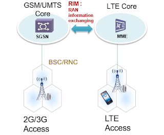
To support Flash CS Fallback, eNodeB requires exchange information between E-UTRAN and GERAN/UTRAN through the core networks
- Flash CS Fallback is defined in 3Gpp R9 .With this function, SIB can be included into the ”RRC connection Release” during the redirection procedure. This is achived by the RIM procedure. with RIM, eNodeB can get information from GERAN/UMTS.
- The RIM procedure supports two information exchange modes:
 Single Report and Multiple Report. 
- In Single Report mode, the source sends a request, and then the target responds with a single report.
- In Multiple Report mode, the target responds with a report after receiving a request from the source, and it also sends a report to the source each time the system information changes.

- the RIM procedure in Multiple Report mode is performed as follows: After an E-UTRAN cell is set up, the eNodeB sends a request for system information to neighboring UTRAN cells. After a neighboring UTRAN cell receives a request or the system information changes, this cell sends the system information to the eNodeB.

- If an eNodeB supports flash CS Fallback, it requires the system information of neighboring UTRAN cells to perform a redirection. If the serving cell does not have that information, the eNodeB must initiate an RIM procedure in Single Report mode to acquire the system information.

CS Fallback Based on PS Handover(UMTS)


Once a LTE UE initiates a voice request, MME informs the eNodeB to perform a CS Fallback procedure:
The UE sends the MME an NAS message Extended Service Request to initiate a CS service.
The MME sends an S1-AP Request message to instruct the eNodeB to initiate a CS Fallback procedure (If the MME supports the LAI-related feature, the MME also delivers the LAI to the eNodeB).
The eNodeB initiates the preparation phase for a PS handover. If the preparation is successful, the eNodeB instructs the UE to perform a handover.
After the handover, the UE may initiate an LAU or combined RAU/LAU procedure in the UTRAN.
The UE’s context in EPS is released.

CS Fallback Procedure for terminated Calls(UMTS)

CS Fallback procedure for a terminated call is shown in the slide:
The MSC sends a Paging Request message from the CS domain to the MME over the SGs interface. Then, either of the following occurs:
-If the UE is in idle mode, the MME sends a Paging message to the eNodeB. Then the eNodeB sends a Paging message over the Uu interface to inform the UE of an incoming call from the CS domain, then UE initiates a connection establish procedure.
- If the UE is in active mode(connected), the MME sends the UE an NAS message to inform the UE of an incoming call from the CS domain.
- The UE sends an Extended Service Request message containing a CS Fallback Indicator after receiving the paging message from the CS domain.
- The MME instructs the eNodeB over the S1 interface to perform CS Fallback.
- The subsequent steps are similar to the originated CS Fallback to UTRAN.
- The service request message from the UTRAN cell to UMTS CN is considered as the Paging Response message.


Visit our Facebook Page 

CS Fallback to GERAN

Based on the capabilities of UEs and networks, the following mechanisms are available for an eNodeB to perform CS Fallback to GERAN
- CS Fallback based on PS redirection
Flash CS Fallback(with RIM)
- CS Fallback based on PS handover
Flash CS Fallback(Blind handover)
- CS Fallback based on CCO/NACC


-The procedures of CS Fallback to GERAN are similar with those of to UTRAN, just the CCO/NACC is particularly for GSM.
-During CS Fallback based on CCO/NACC, the eNodeB receives a CS Fallback Indicator from the MME, and then it sends a Mobility From EUTRA Command message to the UE over the Uu interface. The message contains information about the operating frequency, ID, and system information of a target GERAN cell. The UE searches for the target cell based on the information it received, and then it performs initial access to the cell to initiate a CS service.

CS Fallback Based on CCO/NACC(GERAN)

- The Cell Change order (CCO) procedure with Network Assisted Cell Change (NACC) is an alternative to the RRC Connection Release with Redirection procedure used for CS Fallback. The main difference is that the UE is moved to the target RAT whilst in RRC Connected Mode, also MME can get some response(UE Context Required) from GSM so as to trigger the UE context release procedure.
- In this CS Fallback procedure, the eNodeB sends a “Mobility From EUTRA Command” message over the Uu interface to indicate the operating frequency and ID of the target GERAN cell. If the source cell has the system information of the target cell, the system information is also carried in the message.

CSFB For SMS and LCS service

SMS :short message
LCS : location service
- SMS services are unknown to the eNodeB because SMS messages are encapsulated in NAS messages. During interworking with the UTRAN, SMS messages are exchanged between the MME and the MSC over the SGs interface. Because a UE does not require fallback to the UTRAN/GERAN to perform an SMS service, the SMS over SGs function can be used in a place covered only by the E-UTRAN.
- After a UE initiates an LCS request, the MME performs an attach or combined TAU/LAU procedure to inform the UE of the LCS capability of the EPS. If the EPS does not support LCS, the UE falls back to the UTRAN to initiate LCS under the control of the EPS. The CSFB procedure is the same as the procedure for CSFB to UTRAN for mobile-originated calls.

Visit our Facebook Page 

VAMOS (Voice services over Adaptive Multi-user channels on One Slot, Modulation and Power Control for Vamos) IN GSM part3

BY engineer :abdallah Saleh 

Adaptive QPSK (AQPSK) Modulation

In 1986 P. Laurent showed that Gaussian Minimum Shift Keying (GMSK) phase modulation could be approximated by Binary Phase Shift Keying amplitude modulated pulse.

VAMOS extends Laurent’s approximation method to represent the superposition of two GMSK signals as a single AQPSK modulated signal.

Symbol Rotation:

The modulating symbols are continuously rotated with 𝜑 radians per symbol to avoid transitions through the origin (ensure that the envelope of the signal does not go instantaneously close to zero). This minimizes the variations in the modulating signal which in turn minimizes the linearity requirements of the amplifier.
(i.e. each phase modulated symbol is additionally phase shifted by 𝜑 radians per symbol).

Symbol rotation φ depending on modulation:


AQPSK use π/2 symbol rotation to imitate GMSK, so legacy GMSK SAIC handsets can receive them separately.

Pulse Shaping:

The process of changing the waveform of transmitted pulses; its purpose is to make the transmitted signal better suited to its purpose or the communication channel, typically by limiting the effective bandwidth of the transmission. 
By filtering the transmitted pulses this way, the inter-symbol interference caused by the channel can be kept in control. In RF communication, pulse shaping is essential for making the signal fit in its frequency band.

facebook page 
                                     Engineering-Academy

 VAMOS DL Power Control

VAMOS Sub-channel Power Control feature adapts the AQPSK modulation constellation to distribute the downlink transmit power between the two sub-channels of the AQPSK modulated carrier. Extra power can be distributed to one of the sub-channels, at the expense of the paired sub-channel. This mechanism is important since it allows legacy mobiles to operate in VAMOS mode. 
The position of the AQPSK symbols, and thus the power distribution between the sub-channels, defined by the Sub-channel Power Imbalance Ratio (SCPIR), are controlled by the VAMOS Sub-channel Power Control.

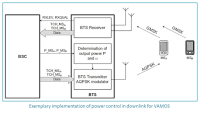
Power Control in downlink for VAMOS is done in two successive stages:

-Determination of the required transmit power levels for both mobile stations MS-A and MS-B according to the radio link measurement reports (RXLEV and RXQUAL) received from these mobiles. The BSS determines the power level P MSA required for MS-A in the first sub-channel and P MSB for MS-B in the second sub-channel.
-Determination of the corresponding AQPSK signal constellation and output power for the AQPSK signal. A control unit in the BTS computes a combination of output power P and α that gives the required combination of P MSA and P MSB in downlink based on the following relationship:   P = P MSA + P MSB = P × cos2 α + P × sin2 α

facebook page 
                                     Engineering-Academy

VAMOS MS Categories:

For several years now, many mobiles have been equipped with SAIC receivers to improve their resistance against inter-cell interference, i.e. not even with VAMOS in mind. 
In other words, when VAMOS gets deployed one does not have to wait for special VAMOS capable devices to reach a critical mass before the benefits can be seen. However terminals that support VAMOS feature increase performance of the BSS VAMOS feature.
Legacy Non-SAIC:
-Don’t support SAIC algorithm or TSC Set 2
-Can’t be paired with a legacy non-SAIC MS or legacy SAIC MS.
-May be multiplexed on the VAMOS sub-channel in the case of much power offset.
Legacy SAIC:
-Support SAIC algorithm but not support TSC Set 2
-Does not require much power offset.
VAMOS level I:
-Support SAIC algorithm and TSC Set 2
VAMOS level II:
-VAMOS II user devices must cope with strong negative SCIPR values, which will likely require implementation of joint detection techniques in the receiver. Therefore VAMOS I and II requirements will differ by verifying voice performance at different SCPIR proof points. VAMOS I user devices will be tested at SCPIR = -4dB, 0dB and 4dB, whereas VAMOS II user devices will need to fulfill reference performance additionally at SCPIR = -8dB and SCPIR = -10dB.
The VAMOS-aware mobiles are expected to be served on the weaker sub-channels when being multiplexed with legacy mobiles.

Sub-channel Power Imbalance Ratio (SCPIR) is defined by; 
Assuming that MS-B receives the quadrature component and MS-A the in-phase component of the AQPSK signal.

facebook page 
                                     Engineering-Academy

to understand the VAMOS read other parts 

what is the VOLTE ??

VOLTE principals 

The LTE voice solution is as follows:

-Voice solution based on dual-standby UEs:
A dual-standby UE is capable of receiving or sending signals in both E-UTRAN and GERAN or UTRAN. Dual-standby UEs automatically select GERAN or UTRAN to perform voice services and select E-UTRAN to perform data services. That is, the E-UTRAN provides dual-standby UEs with only data services.

-Voice solution based on CSFB:
In the initial phase of LTE network deployment, CSFB is a transitional solution to provide voice services for LTE users if the IMS is not yet deployed.With the CSFB solution, when a UE initiates a CS service in the E-UTRAN, the MME instructs the UE to fall back to the legacy CS domain of the GERAN or UTRAN before the UE performs the service 


-Voice solution based on the IMS :

This solution is used in the mature stage of the LTE network when the IMS is deployed, With this solution, UEs can directly perform voice services in an LTE network. This solution is also termed as the Voice over LTE (VoLTE) solution. The LTE network must support SRVCC or PS handover to provide UEs running voice services with continuous services when the UEs move out of an LTE network

VoLTE is the voice service supported by the IP transmission network between calling/called UEs in the E-UTRAN and the IMS. That is, with VoLTE, calling/called UEs in the LTE network can perform voice services directly.
VoLTE provides UEs in the E-UTRAN with voice services, without the need of falling back to GERAN or UTRAN. VoLTE features the following characteristics:

-Higher spectral efficiency

-Better user experience, such as lower access delay and better voice quality


Visit our Facebook Page 

Network Architecture


MME: mobility management entity
 S-GW: serving gateway
SGSN: serving GPRS support node
 HSS: home subscriber server
PCRF: policy and charging rule function
 PDN Gateway: packet data network gateway
IP multimedia subsystem (IMS) includes multiple network elements (NEs). These NEs perform voice session control and multimedia negotiation between the calling and called UEs


Speech Codec Scheme and Traffic Model

AMR

-AMR is an audio data compression scheme optimized for speech coding and is now widely used in GERAN and UTRAN. AMR is classified into adaptive multirate wideband (AMR-WB) and adaptive multirate narrowband (AMR-NB).

AMR-NB has eight speech coding rates.

They are 12.2 kbit/s, 10.2 kbit/s, 7.95 kbit/s, 7.4 kbit/s, 6.7 kbit/s, 5.9 kbit/s, 5.15 kbit/s, and 4.75 kbit/s.

AMR-WB has nine speech coding rates.

They are 23.85 kbit/s, 23.05 kbit/s, 19.85 kbit/s, 18.25 kbit/s, 15.85 kbit/s, 14.25 kbit/s, 12.65 kbit/s, 8.85 kbit/s, and 6.6 kbit/s.

There are two VoLTE traffic states:


Talk spurts
During talk spurts, the uplink of UEs transmits voice packets or the downlink of UEs receives voice packets. Voice packets are transmitted at intervals of 20 ms, and the packet size is determined by the speech coding rate.

Silent period
During silent periods, the UE transmits silence insertion descriptor (SID) frames or receives SID frames at intervals of 160 ms. For different AMR speech codec rates, the SID frame sizes are all 56 bits.

The differences between talk spurts and silent period are as follows:

The size of voice frames is greater than the size of SID frames.
The interval between neighboring voice frames is different from the interval between SID frames.
The eNodeB distinguishes between voice frames and SID frames based on the preceding differences

G.711
G.711, also known as pulse code modulation (PCM), is primarily used in fixed-line telephony. It supports a coding rate of 64 kbit/s.

G.729
G.729, known for the high voice quality and low delay, is widely used in various domains of data communications. It supports a coding rate of 8 kbit/s.

G.726
G.726 supports coding rates of 16 kbit/s to 40 kbit/s. The most commonly used rate is 32 kbit/s. In actual application, voice packets are sent at intervals of 20 ms.

The VOLTE Feature will be explained sooooon 

Visit our Facebook Page 


3G Optimization Paging Reception

The purpose of the paging procedure is as follows:


-The core network (CN) originates the paging procedure to inform selected UEs of service requests and to trigger reading of updated UTRAN system information.
-The UTRAN originates the paging procedure to trigger state transitions from URA_PCH to CELL_FACH or idle mode for selected UEs.

1-Paging Types 

Paging UE in Idle, CELL_PCH, URA_PCH State (Type 1)

+When an UE is in idle, CELL_PCH, or URA_PCH state, UTRAN sends a paging message to the UE through the PCCH.

Paging type 1 procedure is used to transmit paging information to the selected UEs in idle mode, CELL_PCH or URA_PCH state using the PCCH. With this feature, upper layers in the network can:

-Trigger UE establishing an RRC signaling connection.
-Trigger CELL UPDATE procedure of UE in CELL_PCH or URA_PCH state.
-Trigger reading of updated system broadcast of UE in idle mode, CELL_PCH or URA_PCH state.
-Trigger releasing signaling connection of UE in CELL_PCH or URA_PCH state.
+When the CN sends data to UEs in CELL_PCH or URA_PCH state, the UTRAN shall repeat the paging process five times in case of a paging failure towards a UE for some reasons (For example, the UE has moved out of the UTRAN and transferred to an inter-RAT network.). If the UTRAN still fails to page the UE, the UTRAN considers that the paging towards the UE fails and releases the RRC connection with the UE.

Paging UE in CELL_FACH, CELL_DCH State (Type 2)

The network can control the UE in CELL_FACH or CELL_DCH state which has DCCH with paging type 2 procedures. In paging type 2, UTRAN sends a paging message to the UE in CELL_FACH or CELL_DCH state through the DCCH or FACH.

 Reception Technology

+To reduce power consumption, the UE can read the information from the PICH only at a particular time. This is known as the Discontinuous Reception (DRX) technology. The interval between two consecutive receiving occasion is called DRX cycle.

+For Frequency Division Duplex (FDD), the DRX cycle length shall be 2k frames, where k is an integer and is determined by the following three parameters:

-CN domain specific DRX cycle length for CS
-CN domain specific DRX cycle length for PS
-UTRAN DRX cycle length coefficient

The description of the parameters is as follows:

-CN domain specific DRX cycle lengths
facebook page 

-The UE may be attached to different CN domains with different CN domain specific DRX cycle lengths. The UE shall store these lengths for all CN domains where the UE is attached and shall use the shortest one.
-UTRAN DRX cycle length

+For a UE in idle mode, the DRX cycle length equals the shortest value of the stored DRX cycle length for the CN domains where the UE is attached, with no signaling connection established.

+For a UE in CELL_PCH state or URA_PCH state, the DRX cycle length equals the shortest value of the following lengths:

-UTRAN DRX cycle length
-Any of the stored DRX cycle length for the CN domains where the UE is attached, with no signaling connection established
If you set a great DRX cycle length coefficient, the period for UE detect paging information will be long; therefore, the UE can reduce the power consumption, but the delay for responding to a paging will be long.

why we Use Channel Quality Indicator (CQI) in UMTS not only the ECNO??

CQI report 

UE sends a Channel Quality Indicator (CQI) on the uplink (HS-DPCCH)

CQI

-Estimates the number of bits that can be transmitted to the UE using a certain assumed HS-PDSCH -power with a block error rate of 10%
-UE receiver performance
Good UE receiver can report that it can receive more bits than a Bad UE receiver implementation for the same channel conditions.


PCPICH_RX
Received power of the P-CPICH
Г
Measurement Power Offset MPO
Cell level parameter hsMeasurementPowerOffset
Reference power adjustment
Given by Table 7A, 7B, 7C, 7D, 7E, 7F or 7G depending on the UE category.

Physical layer procedures (FDD)

CQI algorithm indicates 

-Transport block size
-Number of HS-PDSCH codes
-Modulation Type
-HS-PDSCH Power

HSDPA Scheduler algorithm indicates

 -Which UE to transmit to in the TTI, 
-Available HS-PDSCH transmission power, Available number of HS-PDSCH codes. 
-It does not indicate how much data to transmit.
CAT6
CQI Value
Transport Block Size
Number of HS-PDSCH
Modulation
Reference Power Adjustment
1
137
1
QPSK
0
2
173
1
QPSK
0
3
233
1
QPSK
0
4
317
1
QPSK
0
5
377
1
QPSK
0
6
461
1
QPSK
0
7
650
2
QPSK
0
8
792
2
QPSK
0
9
931
2
QPSK
0
10
1262
3
QPSK
0
11
1483
3
QPSK
0
12
1742
3
QPSK
0
13
2279
4
QPSK
0
14
2583
4
QPSK
0
15
3319
5
QPSK
0
16
3565
5
16-QAM
0
17
4189
5
16-QAM
0
18
4664
5
16-QAM
0
19
5287
5
16-QAM
0
20
5887
5
16-QAM
0
21
6554
5
16-QAM
0
22
7168
5
16-QAM
0
23
7168
5
16-QAM
-1
24
7168
5
16-QAM
-2
25
7168
5
16-QAM
-3
26
7168
5
16-QAM
-4
27
7168
5
16-QAM
-5
28
7168
5
16-QAM
-6
29
7168
5
16-QAM
-7
30
7168
5
16-QAM
-8


Why CQI?

Back to  Basics:

PN codes (distinguish each Base Station)

-Not orthogonal
-High cross correlation properties
-PN1 * PN2  ≠ 0 (mini. output)  


Channelization Codes (distinguish data channels Coming from each Base Station)

-Orthogonal Codes
-OC1 * OC2 = 0


-Ec/No for most of us is quality measurement metric. 
-It gives us how good or bad the link quality is.
-However by definition it is confusing
RSCP
-Received signal code power
-Received power level of pilot channel of a one cell (dBm/mW)
-Using RSCP we can compare different cells
-Using RSCP handover and cell reselection decisions can be taken
RSSI
-Signal power over the complete 5MHZ carrier which include all components received 
-Signal from the current cell and neighboring cells on the same frequency
-Theoretically in an isolated cell having only CPICH power with no other channels  
RSSI ≈ CPICH power 
-RSSI will change if the carrier use the DCH or the common channels

CPICH  Ec/No
-Pilot channel quality ,energy per chip over total received power spectral density
Ec/No= RSCP/RSSI
-The Better this value the better the signal can be distinguished from the over all nosie
-Always negative 
-Using Ec/No we can compare different cells
-Using Ec/No handover and cell reselection decisions can be taken

Visit our Facebook Page 

Noise power spectral density 
-Interfering power  
-Non interfering power 
-Thermal noise
-Test bed being served by single cell
Ec/No of UE is 
Measure of PCPICH =RSCP
Measure of total wide band power =RSSI

Assume that UE is in Test bed being served by single cell`
-Cell MAXTXPOWER  20 watt (43 dBm)
-Assuming that 10 % of the cell power is dedicated for CPICH 2 watt (33 dBm)
-If you have no DCH or HS channels 
-Ec/No= 10 log (CPICH Power/Total transmitted power)
-Ec/No=10 log (2w/2w)= 10 log 1 = 0

Assume that you start HS session
-Ec/No= 10 log (CPICH Power/Total transmitted power)
-Ec/No=10 log (2w/20w)= -10 dB (Poor value)
-Ec/No will always give a false value for an HSDPA user


CQI Adjustment


Deviating CQI reports lead to faulty decisions

-CQI accuracy will continue to vary depend on :
-UE model 
-UE vendor

Deviating CQI

-UE that consistently overestimates the channel quality
+Scheduled too often, at the price of other users. 
+Experience a block error rate that is higher than the target 10%, with more retransmissions and reduced system throughput and increased service delay
-UE instead underestimates the channel quality
 +Scheduled too seldom. 
+Experience a Block error rate will be lower than 10%, which will lead to lower transmitted data rates than possible and hence reduced system throughput.

In both cases, both system throughput and end-user experience of the service is negatively impacted.

To avoid the negative system impact due to inaccurate CQI reports, 
-CQI adjustment algorithm 
+RBS works on the ACKs and NACKs received from the UE to determine if the UE is overestimating or underestimating the channel quality. 
+The algorithm make every effort to achieve a block error rate of 10%

-The output from the adjustment algorithm is CQIadjusted, 
-The CQI adjustment algorithm is an optional feature and can be enabled on cell level through parameter cqiAdjustmentOn

Visit our Facebook Page